Top-oil temperature indication for oil-immersed transformers
The final implementation follows the confirmed model code, outline drawing and terminal diagram.

Oil Temperature Indicators manufacturer
An OTI gauge for transformer top-oil temperature indication, adjustable cooling and alarm contacts, and remote measurement output.
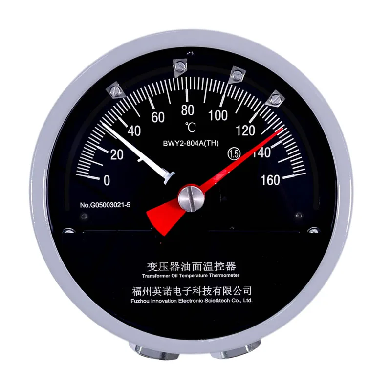
Confirm how the selected configuration will indicate temperature, operate contacts and communicate with the remote system.
The final implementation follows the confirmed model code, outline drawing and terminal diagram.
The final implementation follows the confirmed model code, outline drawing and terminal diagram.
The final implementation follows the confirmed model code, outline drawing and terminal diagram.
Use these values for initial comparison, then confirm the selected suffix, options and project interfaces in the current model documents.
| Operating ambient | -40°C to +80°C |
|---|---|
| Relative humidity | Up to 95% at 25°C |
| Measuring range | -20°C to 140°C |
| Accuracy | Class 1.5; stated maximum error ±2.4°C |
| Switch contacts | 2-4 adjustable contacts |
| Switch rated power | AC 220 V / 5 A |
| Temperature bulb | Φ14 × 150 mm |
| Mounting thread | M27 × 2 mm |
| Remote signal options | Pt100; 4-20 mA by selected configuration |
| Protection grade | IP55 |
The BWY2 oil temperature indicator, or OTI gauge, measures the temperature at a transformer top-oil pocket. It provides a local pointer display and can operate adjustable contacts for cooling stages or an over-temperature alarm. A Pt100 output supports remote indication, while selected configurations can provide a transmitter or digital display.
Top-oil temperature is an important thermal operating value, but it is not the same as winding hot-spot temperature. The OTI records the oil condition at its sensing pocket. A WTI adds a load-dependent simulated rise. This distinction should remain clear in specifications, panel labels and alarm philosophy.
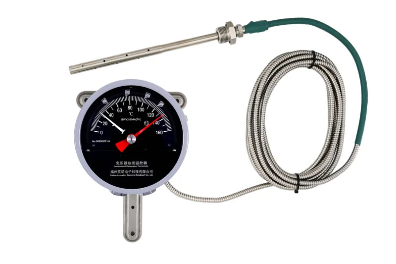
A sealed sensing system links the temperature bulb, capillary and elastic measuring element. Temperature changes alter the sensing medium and move the indicator mechanism. Adjustable microswitches change state when the pointer mechanism reaches their configured set points.
The bulb is normally inserted into a thermometer pocket in the top-oil region. The pocket arrangement and thermal interface affect response. The selected capillary length must reach the mounting position without tight bends or unsupported loops.
Confirm the full BWY2 model, measuring scale, switch quantity, contact use, output signal, capillary length, bulb and thread, mounting layout and need for a remote display.
For replacement work, compare the existing dial scale, terminal diagram and dimensions. Similar-looking BWY and BWY2 variants can use different contacts or output arrangements.
Fill or prepare the thermometer pocket according to the transformer design and insert the bulb to its intended depth. Fix the instrument vertically and route the capillary with mechanical protection.
Test the pointer response, adjustable contacts and Pt100 or transmitter loop before the transformer enters service. Record the final set points and terminal assignments in the commissioning file.
Confirm the measurement point, contact logic, output and mechanical interface against the transformer project documents.
Confirm the measurement point, contact logic, output and mechanical interface against the transformer project documents.
Confirm the measurement point, contact logic, output and mechanical interface against the transformer project documents.
Confirm the measurement point, contact logic, output and mechanical interface against the transformer project documents.
Specifications and available options vary by model configuration. Request the current datasheet, outline drawing and terminal diagram before approving an order.
Review other models for the same transformer temperature measurement and control function.
Compare oil temperature indicatorsReview how OTI and WTI contacts support transformer cooling stages and protection logic.
Transformer cooling and protection applicationCompare existing codes, outputs, capillary routing and mounting interfaces before a controller replacement.
Transformer OTI and WTI replacement guideCheck available management-system, conformity and qualification materials for procurement review.
Certification and qualification documentsDirect engineering contact
Email the transformer type, model reference, measuring range, output, switch contacts, capillary length, quantity and destination country. INNO will reply with the applicable configuration details.