How to Select a Transformer Winding Temperature Indicator
Define the simulated winding temperature scale, CT secondary input and heating configuration first. Then specify cooling, alarm and trip contacts, Pt100 or 4-20 mA output, compound transmitter, capillary, mounting and replacement interfaces.
Define the transformer measurement and control functions
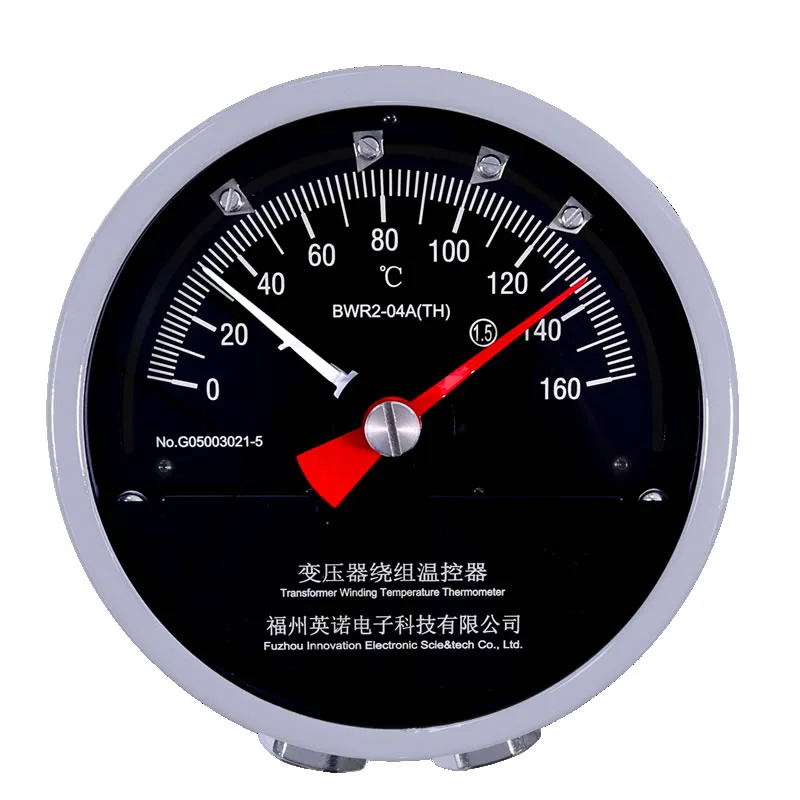
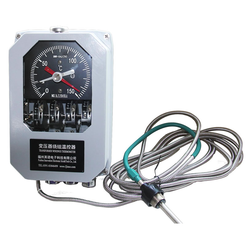
Top-oil temperature, traditionally simulated winding temperature and direct winding hot-spot temperature are different values. Define the required local display, cooling stages, alarm or trip contacts, remote output and receiving equipment before comparing suffixes.
Provide complete mechanical and electrical interfaces
Send the transformer type, existing model, measuring range, contact duty, Pt100 or 4-20 mA requirement, supply, capillary length, bulb, thread, mounting dimensions, quantity and destination country. Replacement projects should include nameplate, terminal and installation photographs.
Control the final model specification
BWY, BWY2, BWR and BWR2 family names can cover several contact and output configurations. Confirm the complete model code against the current datasheet, outline drawing and terminal diagram before purchase.
For system integration, review substation remote transformer temperature monitoring and the transformer temperature controller wiring guide.