How Does Transformer Cooling, Alarm and Trip Control Work?
Give every contact a defined job
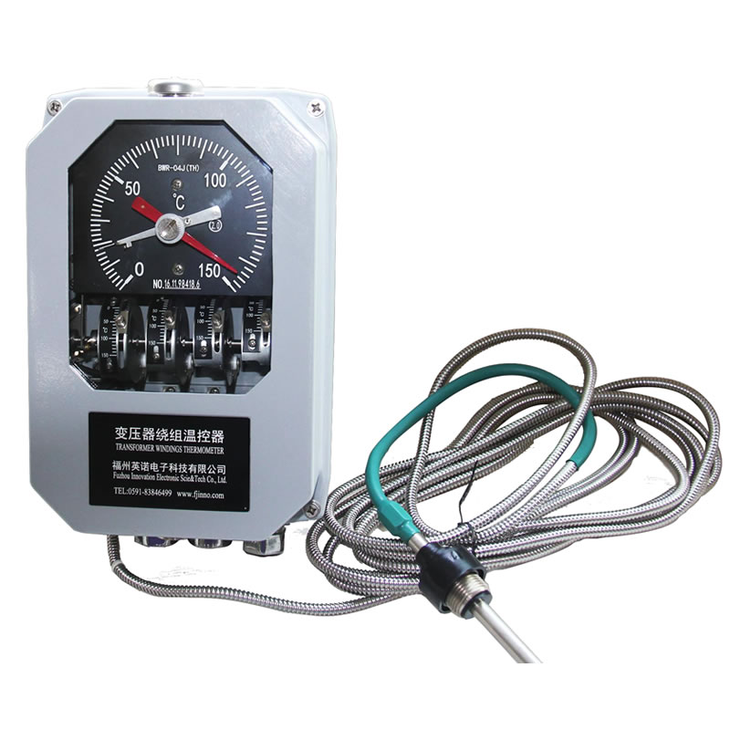
The instrument may provide two, four or six adjustable contacts. Each contact should have a written function such as fan stage one, fan stage two, high-temperature alarm or trip initiation. The terminal drawing must show whether an interposing relay is used.
The contact rating printed for an instrument does not automatically authorize direct motor switching. Review the actual inductive load, control voltage and relay design. Interposing relays can separate the measuring instrument from higher-duty circuits.
Choose set points from transformer engineering data
Cooling and alarm set points should come from the transformer design, specified temperature limits and protection study. Copying a common value from another transformer can cause unnecessary cooling or delayed protection.
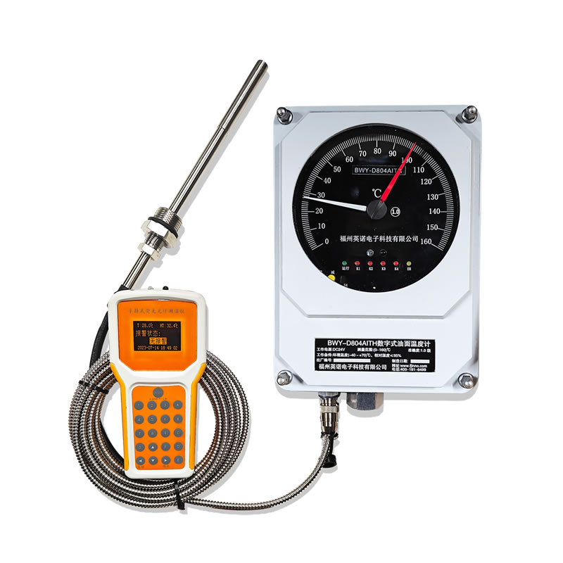
The WTI reflects a load-related simulated winding value, while an OTI reflects top oil. Their contacts may therefore use different settings and serve different purposes. The commissioning record should state both the set point and the variable it represents.
Manage switching differential and sequence
Mechanical temperature switches include a switching differential. A contact that starts a fan at a rising temperature will release at a lower value. The differential prevents rapid cycling but must be considered when coordinating stages.
Sequence the stages so cooling starts before alarm and alarm occurs before any temperature-based trip, subject to the approved design. Test the actual switch behavior rather than assuming the pointer setting equals the final operating point exactly.
Prove the logic before service
Functional testing should trace every contact from the instrument terminal to the final fan, pump, annunciator or protection relay input. Confirm contact state, wiring, interlocks and fail-safe behavior.
Label and seal approved set points where required. Periodic maintenance should test contact operation and inspect for capillary damage, moisture ingress or pointer error.
What Project Risks Should Be Checked?
Switching motor loads beyond contact ratings
Resolve this point in the selection sheet, drawings and commissioning procedure before the transformer enters service.
Using identical set points for different transformer designs
Resolve this point in the selection sheet, drawings and commissioning procedure before the transformer enters service.
Assigning a WTI trip from an unverified CT circuit
Resolve this point in the selection sheet, drawings and commissioning procedure before the transformer enters service.
Leaving no hysteresis or functional test record
Resolve this point in the selection sheet, drawings and commissioning procedure before the transformer enters service.