Default 0-150°C scale with optional 0-160°C configuration
The final implementation follows the confirmed model code, outline drawing and terminal diagram.

Winding Temperature Indicators manufacturer
A BWR winding thermometer family for simulated winding temperature, switch control and remote 4-20 mA configurations.
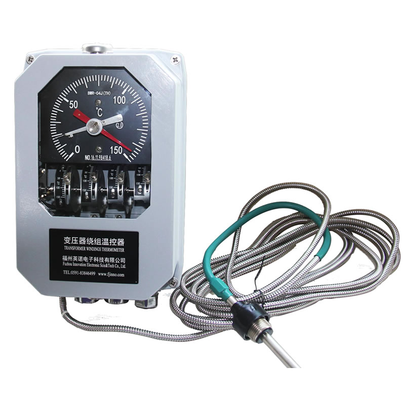
Confirm how the selected configuration will indicate temperature, operate contacts and communicate with the remote system.
The final implementation follows the confirmed model code, outline drawing and terminal diagram.
The final implementation follows the confirmed model code, outline drawing and terminal diagram.
The final implementation follows the confirmed model code, outline drawing and terminal diagram.
Use these values for initial comparison, then confirm the selected suffix, options and project interfaces in the current model documents.
| Referenced model | BWR-04J(TH) |
|---|---|
| Default measuring range | 0°C to 150°C |
| Optional range | 0°C to 160°C |
| Accuracy | Class 1.5; stated detection-point error ±2.25°C |
| Switching error | ±2°C |
| Switch rating | AC 220 V / 5 A; DC 220 V / 3 A |
| Output for J configuration | 4-20 mA |
| Power supply | AC 220 V ±10%, 50-60 Hz |
| Operating ambient | -40°C to +55°C; altitude up to 2,000 m |
| Protection grade | IP55 |
| Bulb and thread | Φ14 × 150 mm; M27 × 2 mm |
| Standard capillary | 5 m |
The BWR-04 and BWR-06 families are winding temperature controllers for oil-immersed transformers. They use a top-oil sensing system and a load-current thermal simulation element to provide a winding-temperature indication. Model suffixes identify output and contact configurations, so the exact suffix is required for procurement.
The referenced BWR-04J(TH) configuration provides a 4-20 mA current signal. Other members of the family may use different outputs, contact quantities or special-environment suffixes. The published family range is useful for initial selection, but the final quotation must follow a confirmed datasheet and drawing.
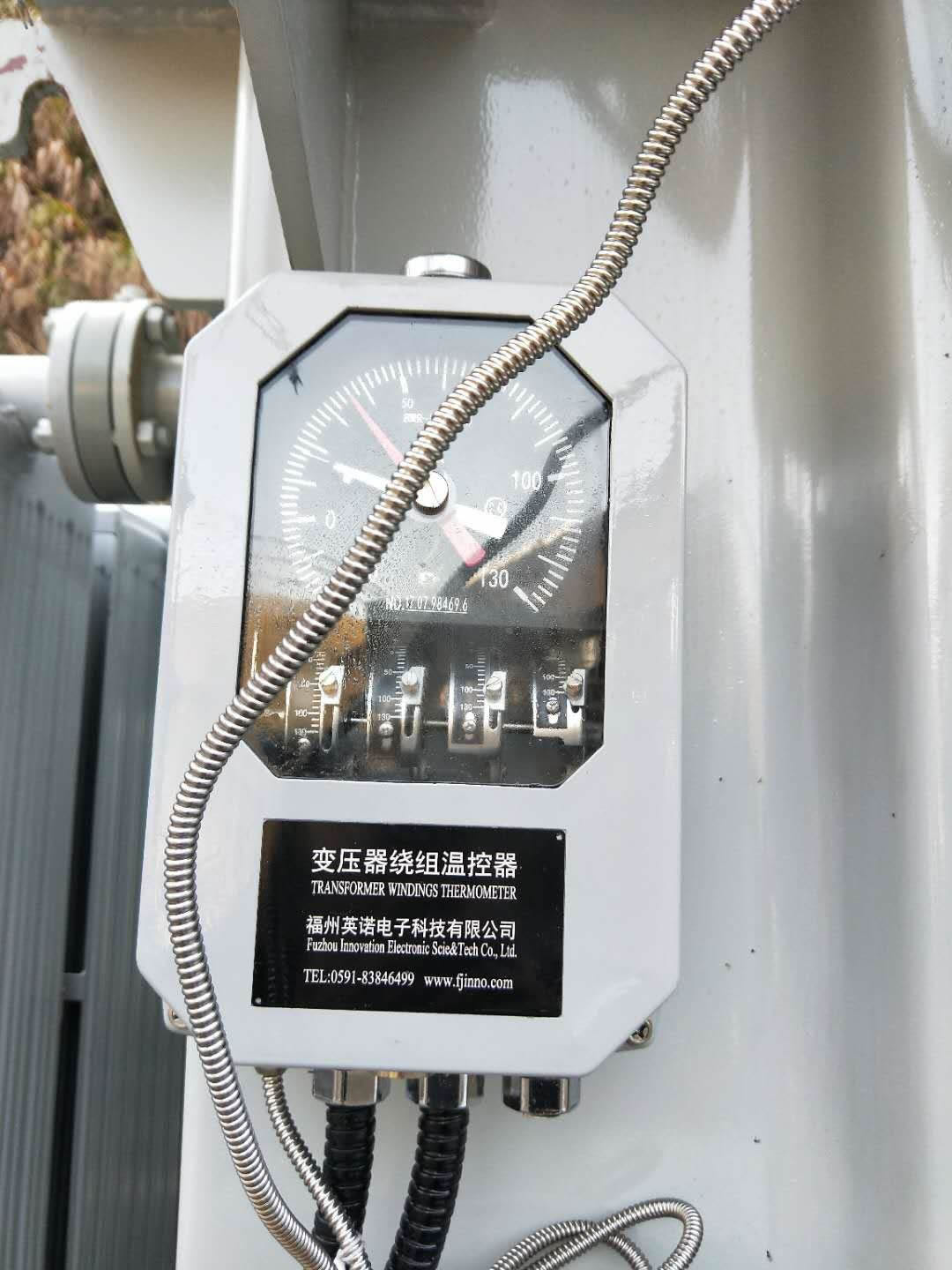
The sensing bulb follows top-oil temperature while the load-current converter drives an internal heating element. The additional heating represents winding-to-oil temperature rise. The mechanical system sums both effects and moves the pointer.
Switch contacts can control cooling, initiate an alarm or contribute to trip logic. The 4-20 mA output allows a compatible remote display or monitoring system to receive the indicated temperature.
Send the existing BWR-04 or BWR-06 code, scale, contact quantity, CT input, output, supply, capillary length and installation drawing.
Specify whether the instrument must match an existing mounting footprint or whether a new transformer design can use the current standard dimensions.
Keep the instrument vertical and protect the capillary. Verify the sensing bulb, thread and pocket depth before installation.
Commission the local pointer, each switch contact, CT circuit and remote current loop. Confirm polarity and scaling at the receiving instrument.
Confirm the measurement point, contact logic, output and mechanical interface against the transformer project documents.
Confirm the measurement point, contact logic, output and mechanical interface against the transformer project documents.
Confirm the measurement point, contact logic, output and mechanical interface against the transformer project documents.
Confirm the measurement point, contact logic, output and mechanical interface against the transformer project documents.
Specifications and available options vary by model configuration. Request the current datasheet, outline drawing and terminal diagram before approving an order.
Review other models for the same transformer temperature measurement and control function.
Compare winding temperature indicatorsReview how OTI and WTI contacts support transformer cooling stages and protection logic.
Transformer cooling and protection applicationCompare existing codes, outputs, capillary routing and mounting interfaces before a controller replacement.
Transformer OTI and WTI replacement guideCheck available management-system, conformity and qualification materials for procurement review.
Certification and qualification documentsDirect engineering contact
Email the transformer type, model reference, measuring range, output, switch contacts, capillary length, quantity and destination country. INNO will reply with the applicable configuration details.